
Safety Valves Explained
Ensuring Overpressure Protection in Critical Systems
Introduction to Safety Valves
A safety valve is a crucial safety device designed to protect pressure-containing equipment (like boilers, pressure vessels, and piping systems) from exceeding a predetermined safe pressure limit. It automatically discharges a volume of fluid (gas, vapor, or liquid) to reduce the excess pressure, thereby preventing catastrophic failures, equipment damage, and potential harm to personnel and the environment. Safety valves are distinct from relief valves primarily by their rapid opening or “pop” action, especially in gas or vapor service.
Working Principle: Automatic Overpressure Relief
Safety valves operate automatically when system pressure reaches a set point:
- Normal Operation (Closed): Under normal operating conditions, the system pressure acting on the valve disc is less than the force exerted by a pre-set spring (or pilot pressure). The disc remains seated, preventing flow.
- Set Pressure Reached (Opening): As system pressure increases and reaches the valve’s set pressure, the force on the disc overcomes the spring force.
- Rapid Opening (“Pop” Action): For compressible fluids (gases/vapors), the disc lifts rapidly and fully (pop action) due to the design of the disc and nozzle (huddling chamber effect), allowing a large volume of fluid to escape quickly. For liquids, the lift is generally proportional to the overpressure.
- Pressure Reduction & Reseating: As fluid is discharged, system pressure drops. When it falls below the set pressure by a certain amount (blowdown), the spring force overcomes the system pressure, and the disc reseats, stopping the flow.
CLOSED (Normal Pressure)
OPEN (Overpressure)
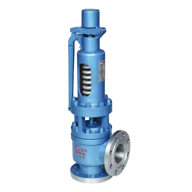
Key Components of a Safety Valve
Body
The main pressure-containing structure with inlet and outlet connections.
Bonnet
Covers the spring and stem assembly. Can be open or closed type.
Disc (or Piston)
The closure element that seals against the seat to prevent flow during normal operation and lifts to relieve pressure.
Seat (Nozzle)
The stationary part within the valve body against which the disc seals. The inlet nozzle forms the primary flow passage.
Spring
Provides the closing force on the disc. Its compression is adjusted to determine the set pressure.
Stem (Spindle)
Transmits the spring force to the disc and guides the disc’s movement.
Adjusting Screw/Bolt
Used to compress the spring and set the opening pressure of the valve.
Lifting Lever (Optional)
Allows for manual operation to test the valve’s functionality or relieve pressure manually (if permitted by code).
Main Types of Safety Valves
Spring-Loaded Safety Valves
The most common type. A spring holds the disc against the seat.
- Conventional: Bonnet is open to discharge. Performance affected by backpressure.
- Balanced Bellows/Piston: Incorporates a bellows or piston to isolate the spring from backpressure, ensuring consistent set pressure regardless of downstream conditions.
Pilot-Operated Safety Valves (POSV)
Uses system pressure itself, controlled by a small pilot valve, to hold the main disc closed. When set pressure is reached, the pilot valve actuates, causing the main valve to open.
- Can operate closer to the set pressure without leakage (tighter seat).
- Less susceptible to chatter.
- Suitable for larger sizes and higher pressures.
Key Terminology
- Set Pressure: The inlet static pressure at which the valve begins to open (or “pop” for gas/vapor service).
- Overpressure: The pressure increase above the set pressure allowed for the valve to achieve full lift and rated capacity (typically 3-10% for ASME Section VIII valves).
- Blowdown: The difference between the set pressure and the reseating pressure. Expressed as a percentage of set pressure or a pressure value.
- Lift: The distance the disc moves away from the seat when the valve is open.
- Chatter: Rapid opening and closing of the valve disc, often due to improper sizing, incorrect blowdown setting, or excessive inlet/outlet pressure drop.
- Simmer (Warn): Audible or visible leakage just below the set pressure, indicating the valve is close to opening.
- Accumulation: The pressure increase over the Maximum Allowable Working Pressure (MAWP) of the vessel during discharge through the safety valve (limited by codes).
- Capacity (Relieving Capacity): The rate of flow (e.g., kg/hr, SCFM) the valve can discharge at a specified overpressure.
Advantages & Disadvantages
Advantages
- Automatic operation, providing reliable overpressure protection.
- Relatively simple and robust design for spring-loaded types.
- Wide range of sizes, materials, and set pressures available.
- Cost-effective solution for safety.
- Pilot-operated valves offer tight shutoff and operation closer to set pressure.
- Essential for meeting safety codes and regulations (e.g., ASME, API).
Disadvantages/Cautions
- Spring-loaded conventional valves can be affected by backpressure.
- Potential for chatter if improperly sized or installed.
- Blowdown means system pressure must drop below set pressure before reseating.
- Leakage can occur if seats are damaged or if the valve simmers.
- Pilot-operated valves are more complex and may be sensitive to dirty fluids.
- Requires regular testing and maintenance to ensure functionality.
Common Materials of Construction
Body & Bonnet
- Brass/Bronze (low pressure steam, air, water)
- Cast Iron (low pressure, non-critical)
- Carbon Steel (e.g., ASTM A216 WCB, A105)
- Stainless Steel (e.g., ASTM A351 CF8M/316)
- Alloy Steels (e.g., WC6, WC9, C5, C12)
Trim (Disc, Seat/Nozzle)
- Stainless Steel (e.g., 316SS, 410SS)
- Stellite® overlay (for hardness, erosion resistance)
- Monel®, Hastelloy® (for specific corrosive services)
- Resilient seats (e.g., Viton®, EPDM) for some liquid relief applications (more common in relief valves).
Spring
- Carbon Steel
- Stainless Steel
- Alloy Steel (e.g., Chrome-Vanadium)
- Inconel® (for high temperature/corrosive)
Typical Applications
Safety valves are mandated in numerous systems:
Key Selection Considerations
- Set Pressure: Must be at or below the MAWP of the protected equipment.
- Required Relieving Capacity: Valve must be able to discharge the maximum anticipated overpressure flow rate.
- Fluid State: Gas, vapor, liquid, or two-phase flow influences valve type and sizing.
- Operating & Relieving Temperature: Affects material selection and spring design.
- Backpressure: Superimposed or built-up backpressure can affect conventional valve performance; balanced or pilot valves may be needed.
- Material Compatibility: With process fluid and environment.
- Codes and Standards: ASME Section I (Power Boilers), ASME Section VIII (Pressure Vessels), API 520/521/526/527 are critical.
- Inlet and Outlet Piping Design: Must minimize pressure drop to ensure proper valve operation and prevent chatter.
- Discharge Location & System: Safe venting or collection of discharged fluid.
Installation & Testing/Maintenance Tips
Installation
- Install vertically with the spring housing (bonnet) upwards.
- Inlet piping should be short, direct, and at least the same diameter as the valve inlet.
- Outlet piping must be adequately sized to handle discharge flow with minimal backpressure, and safely routed.
- Ensure no shutoff valves are installed between the protected equipment and the safety valve inlet (unless specific interlocks are in place per code).
- Protect from freezing if handling liquids that can freeze.
Testing & Maintenance
- Regular testing (e.g., lift tests, set pressure verification) as per codes, regulations, and manufacturer recommendations.
- Frequency depends on service conditions and criticality.
- Keep records of all tests and maintenance.
- Inspect for leakage, corrosion, or damage.
- Overhaul and recertify at specified intervals or if performance issues are noted.
- Only qualified personnel should adjust or repair safety valves. Seals are often applied after setting.
The Ultimate Line of Defense
Safety valves are non-negotiable components in any pressurized system, acting as the final safeguard against potentially catastrophic overpressure events. Their reliable, automatic operation is paramount for protecting lives, assets, and the environment. Proper sizing, selection, installation, and diligent maintenance, all in accordance with relevant codes and standards, are absolutely essential to ensure these critical devices function as intended when called upon.