
Gear Pumps Explained
Reliable Positive Displacement for Various Fluids
Introduction to Gear Pumps
Gear pumps are a common type of positive displacement (PD) pump. They use the meshing action of two or more gears to transfer fluids. As the gears rotate, they create suction at the inlet, trapping fluid between the gear teeth and the casing, and then force it out through the discharge port. Gear pumps are known for their simple design, ability to handle viscous fluids, and providing a relatively constant flow rate regardless of system pressure (within limits).
Working Principle: Trapping and Transferring
The operation is based on the meshing of gears:
- Suction Phase: As the gears unmesh on the inlet side, the volume increases, creating a partial vacuum. Atmospheric pressure (or system pressure) forces fluid into the pump.
- Trapping & Transfer: The fluid is trapped in the pockets between the gear teeth and the pump casing. It is then carried around the periphery of the gears from the inlet to the outlet side.
- Discharge Phase: As the gears mesh again on the outlet side, the volume between the teeth decreases, forcing the trapped fluid out through the discharge port at an increased pressure.
The close tolerances between the gears and the casing are crucial for efficient pumping and preventing internal leakage (slip).
Key Components of a Gear Pump
Gears (Drive & Driven)
The primary pumping elements. One gear (drive gear) is connected to the motor shaft, and it drives the other gear (driven/idler gear).
Housing / Casing
The main body that encloses the gears and forms the pumping chambers. Contains inlet and outlet ports.
Shafts
Support the gears. The drive shaft extends out of the casing to connect to the motor.
Bearings
Support the shafts and allow smooth rotation. Can be sleeve bearings or anti-friction bearings.
Seals
Prevent leakage along the drive shaft where it exits the casing. Lip seals, mechanical seals, or packing are used.
Inlet & Outlet Ports
Connections for the suction and discharge piping.
Main Types of Gear Pumps
1. External Gear Pumps
Feature two identical, intermeshing gears (spur, helical, or herringbone) supported by separate shafts. Fluid is carried between the gear teeth and the casing. Simple and robust.
2. Internal Gear Pumps
One gear (rotor, with external teeth) rotates inside a larger gear (idler, with internal teeth). Fluid is trapped between the teeth of both gears.
Gerotor Type
The inner rotor has one less tooth than the outer rotor (stator). The inner rotor is eccentric to the outer. Creates expanding and contracting pockets. Compact design.
Crescent Seal Type
The inner gear is offset from the center of the larger outer gear, and a crescent-shaped partition separates the suction and discharge ports, sealing between the two gears.
Drive Methods
Gear pumps are typically driven by:
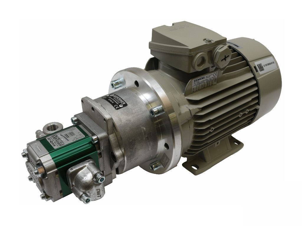
Electric Motors
Most common, AC or DC motors, often close-coupled or via a coupling.
Engines (ICE)
For mobile hydraulic applications or remote locations.
Hydraulic or Pneumatic Motors
In specific system configurations.
Advantages & Disadvantages
Advantages
- Simple design and construction with few moving parts.
- Relatively compact and lightweight for their capacity.
- Can handle a wide range of viscosities effectively.
- Provide a relatively constant, non-pulsating flow.
- Can operate at high pressures.
- Bi-directional flow capability (can pump in either direction).
- Good self-priming capabilities.
- Tolerant of system pressure variations.
Disadvantages
- Not suitable for abrasive solids or large particulates (can cause rapid wear).
- Close tolerances mean they are sensitive to contamination.
- Can be noisy at high speeds.
- Fixed displacement; flow rate is directly proportional to speed (cannot be easily throttled by a valve in the line without a bypass).
- Potential for overpressure if discharge is blocked without a relief valve.
Common Materials of Construction
Housing/Casing
- Cast Iron
- Ductile Iron
- Carbon Steel
- Stainless Steel (316, 304)
- Bronze
- Aluminum (for lightweight applications)
Gears
- Hardened Steel
- Stainless Steel
- Bronze
- Engineered Plastics (e.g., PEEK, Ryton®)
- Tool Steels
Shafts & Bearings
- Shafts: Hardened Steel, Stainless Steel.
- Bearings: Bronze, Carbon/Graphite, Needle Bearings, Ball Bearings (depending on design and fluid).
Typical Applications
Gear pumps are versatile and used in many industries:
Key Selection Considerations
- Fluid Properties: Viscosity is a primary factor. Also consider lubricity, temperature, corrosiveness, and cleanliness.
- Operating Conditions: Required flow rate, discharge pressure, suction conditions.
- Speed Range: Gear pumps have optimal operating speeds for efficiency and longevity.
- Material Compatibility: With the pumped fluid and operating environment.
- Noise Level: Helical or herringbone gears are quieter than spur gears.
- Space and Mounting: Compactness is often an advantage.
- System Protection: Relief valve is essential on the discharge side.
- Cost: Generally cost-effective for their capabilities.
- Maintenance: Relatively simple, but wear can occur with abrasives.
Gear Pump vs. Vane & Centrifugal Pumps
| Feature | Gear Pump | Vane Pump | Centrifugal Pump |
|---|---|---|---|
| Viscosity Handling | Excellent (Wide Range) | Good (Low to Medium) | Poor (Low Viscosity Best) |
| Pressure Capability | High | Moderate | Varies (Low to High with stages) |
| Flow Output vs. Pressure | Relatively Constant | Relatively Constant | Varies with Pressure |
| Solids Handling | Poor (generally) | Limited (some types) | Good (with specific impellers) |
| Self-Priming | Good | Good (some types) | Poor (most types require priming) |
Reliable Workhorses for Diverse Fluids
Gear pumps stand out for their simplicity, robustness, and ability to efficiently handle a wide range of fluid viscosities at various pressures. Their positive displacement nature ensures a consistent flow, making them ideal for metering, hydraulic power, and transfer applications across many industries. While sensitive to abrasives, proper selection of materials and understanding their operational characteristics lead to long and dependable service life.