
Centrifugal Pumps Explained
The Heart of Fluid Transfer Systems
Introduction to Centrifugal Pumps
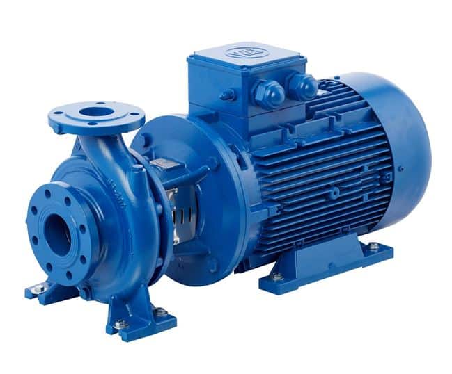
Centrifugal pumps are the most common type of pump used in a vast array of applications worldwide. They belong to the dynamic pump category and operate by converting rotational kinetic energy (from a motor or engine) into hydrodynamic energy of the fluid flow. Their simple design, versatility, wide range of capacities, and relatively low cost make them a preferred choice for moving low-viscosity fluids like water, thin chemicals, and light oils.
Working Principle: Energy Conversion
The operation involves several key steps:
- Fluid Entry: Fluid enters the pump casing near the center of a rotating component called an impeller, typically along its axis (eye of the impeller).
- Impeller Action: The rapidly rotating impeller, driven by a motor, has curved vanes that fling the fluid outwards at high velocity due to centrifugal force. This imparts kinetic energy to the fluid.
- Velocity to Pressure Conversion: As the high-velocity fluid leaves the impeller, it enters the pump casing. The casing is designed to gradually slow down the fluid.
- In a Volute Casing, the cross-sectional area of the casing increases towards the discharge nozzle, converting velocity energy into pressure energy.
- In a Diffuser Casing (common in multistage or turbine pumps), stationary vanes around the impeller guide the flow and efficiently convert velocity to pressure.
- Fluid Discharge: The pressurized fluid is then discharged from the pump outlet.
Fluid Flow Path
Key Components of a Centrifugal Pump
Impeller
The rotating component with vanes that imparts velocity to the fluid. Can be open, semi-open, or closed type.
Casing (Volute/Diffuser)
The stationary housing that encloses the impeller and directs the flow, converting velocity to pressure.
Shaft
Transmits rotational energy from the driver (motor) to the impeller.
Bearings
Support the shaft, reduce friction, and maintain alignment. Can be anti-friction (ball/roller) or sleeve type.
Sealing Mechanism
Prevents leakage along the shaft where it exits the casing. Common types are mechanical seals or gland packing.
Driver (Motor/Engine)
Provides the mechanical energy to rotate the shaft and impeller.
Main Types of Centrifugal Pumps
Based on Flow Direction:
Based on Number of Stages:
Based on Impeller Design:
Other Common Classifications:
Key Terminology & Concepts
- Head (H): The total energy per unit weight of fluid that a pump can impart. Expressed in units of length (e.g., meters, feet). Includes static head, friction head, and velocity head.
- Flow Rate (Q) / Capacity: The volume of fluid pumped per unit time (e.g., m³/hr, GPM).
- NPSH (Net Positive Suction Head):
- NPSHa (Available): The absolute pressure at the pump suction nozzle minus the vapor pressure of the liquid at pumping temperature, plus static liquid level above suction.
- NPSHr (Required): The minimum pressure required at the pump suction to prevent cavitation. This is a characteristic of the pump.
- Crucial: NPSHa must always be greater than NPSHr.
- BEP (Best Efficiency Point): The point on the pump’s performance curve where it operates at its highest efficiency.
- Pump Performance Curve: A graph showing the relationship between head, flow rate, efficiency, NPSHr, and power consumption for a specific pump at a given speed.
- Cavitation: Formation and collapse of vapor bubbles in low-pressure areas within the pump (typically impeller eye), causing noise, vibration, damage, and performance loss.
- Priming: The process of filling the pump casing and suction line with liquid before starting to ensure it can generate suction.
Advantages & Disadvantages
Advantages
- Simple design, fewer moving parts compared to PD pumps.
- Lower initial cost for many applications.
- Smooth, continuous flow (non-pulsating).
- Can handle a wide range of flow rates and heads.
- Relatively low maintenance requirements.
- Compact size for their capacity.
- Can operate against a closed discharge valve for short periods without damage (though not recommended).
Disadvantages
- Not self-priming (most types require initial priming).
- Efficiency drops significantly when operating away from BEP.
- Cannot handle highly viscous fluids efficiently.
- Susceptible to cavitation if NPSHa is insufficient.
- Not suitable for applications requiring very high pressures in a single stage (multistage needed).
- Flow rate varies significantly with changes in system head.
- Generally not suitable for precise metering applications.
Common Materials of Construction
Casing & Impeller
- Cast Iron: General water service, non-corrosive fluids.
- Bronze/Brass: Seawater, some chemicals.
- Stainless Steel (304, 316, Duplex): Corrosive fluids, food/pharma.
- Carbon Steel: Oil & gas, higher pressures.
- Alloy Steels (e.g., Chrome Moly): High temperatures.
- Plastics/Polymers (PP, PVDF, FRP): Highly corrosive chemicals.
Shaft & Seals
- Shaft: Carbon Steel, Stainless Steel (316, 410), Alloy Steels.
- Mechanical Seals: Carbon/Ceramic, Silicon Carbide/Silicon Carbide, Tungsten Carbide/Tungsten Carbide with various elastomers (BUNA, Viton, EPDM, Kalrez®).
- Gland Packing: PTFE, Graphite, Aramid fibers.
Typical Pump Performance Curve
This chart illustrates a typical set of performance curves for a centrifugal pump, showing Head, Efficiency, Power, and NPSHr as a function of Flow Rate.
Typical Applications
Centrifugal pumps are the workhorses in countless fluid transfer scenarios:
Key Selection Considerations
- Required Flow Rate (Q) and Total Dynamic Head (TDH).
- Fluid Properties: Viscosity, density, temperature, corrosiveness, presence of solids/abrasives.
- NPSHa vs. NPSHr: Critical to prevent cavitation.
- Operating Efficiency (BEP): Select a pump that operates close to its BEP for the normal duty point.
- Materials of Construction: For chemical compatibility and wear resistance.
- Pump Speed and Driver Type.
- System Curve: Interaction of pump curve and system resistance curve determines operating point.
- Space Limitations and Installation Orientation.
- Maintenance Requirements and Expected Life.
- Initial Cost and Lifecycle Cost (including energy consumption).
- Industry Standards and Regulations (e.g., API 610 for petroleum industry).
Basic Formulas
Total Dynamic Head (TDH)
Where:
Hs = Static Head (elevation difference)
Hf = Friction Head (losses in pipes/fittings)
Hv = Velocity Head (V²/2g) – often minor
Hp = Pressure Head (difference in surface pressures)
Pump Input Power (Pin) / Brake Horsepower (BHP)
Where:
Q = Flow Rate
SG = Specific Gravity of fluid
Eff = Pump Efficiency (decimal)
C = Constant (depends on units, e.g., 3960 for GPM & ft, 367 for m³/hr & m)
The Ubiquitous Fluid Mover
Centrifugal pumps are the unsung heroes of countless industrial, commercial, and domestic fluid handling systems. Their simple yet effective operating principle, combined with a wide range of designs and materials, makes them adaptable to an incredible variety of applications. While they have limitations, particularly with highly viscous fluids or when precise flow control is needed without external devices, their overall reliability, cost-effectiveness, and broad performance envelope ensure their continued dominance as the primary means of moving liquids worldwide. Proper selection, installation, and operation are key to maximizing their efficiency and lifespan.