Hydraulic Pumps Explained
The Heart of Fluid Power Systems
Introduction to Hydraulic Pumps
Hydraulic pumps are mechanical devices that convert mechanical power (from a prime mover like an electric motor or engine) into hydraulic energy in the form of fluid flow. They are the core component of any hydraulic system, responsible for generating the flow needed to transmit power and actuate cylinders, motors, and other hydraulic machinery. Understanding hydraulic pumps is essential for designing, operating, and maintaining fluid power systems across numerous industries.
Working Principle: Creating Flow, Resisted by Load
Hydraulic pumps operate on the principle of positive displacement:
- Mechanical Input: A prime mover (e.g., electric motor) rotates the pump shaft.
- Creating Vacuum & Suction: The internal mechanism of the pump (gears, vanes, or pistons) creates expanding cavities on the inlet (suction) side. This reduces pressure, allowing atmospheric pressure (or reservoir head) to push hydraulic fluid into the pump.
- Fluid Entrapment & Transfer: The rotating elements trap a specific volume of fluid within these cavities.
- Forced Discharge: As the elements continue to move, the cavities contract on the outlet (discharge) side, forcing the trapped fluid out into the hydraulic system.
- Pressure Generation: Pumps create flow. Pressure is generated by the resistance to this flow within the hydraulic system (e.g., by an actuator, valve, or orifice).
General Key Components of a Hydraulic Pump
Pump Unit (Displacement Mechanism)
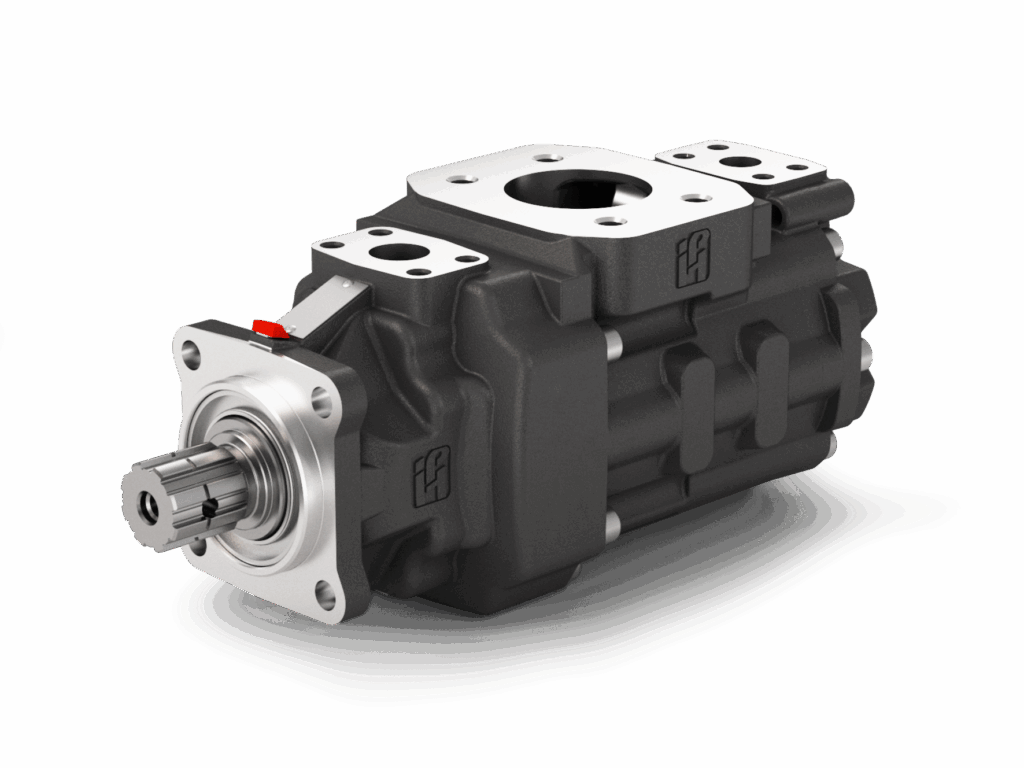
The core elements that displace fluid, e.g., gears, vanes and rotor, or pistons and cylinder block.
Housing / Casing
Encloses the pumping elements and provides inlet/outlet ports. Designed to withstand system pressure.
Drive Shaft
Connects to the prime mover and transmits rotational energy to the pumping elements.
Bearings
Support the shaft and rotating components, reducing friction and handling loads.
Shaft Seals
Prevent leakage of hydraulic fluid along the drive shaft where it exits the casing.
Prime Mover (External)
The source of mechanical power, typically an electric motor or internal combustion engine.
Reservoir (External System Component)
Stores hydraulic fluid, allows for cooling, and helps separate air/contaminants. The pump draws fluid from the reservoir.
Main Types of Hydraulic Pumps
1. Gear Pumps
2. Vane Pumps
3. Piston Pumps
- Bent Axis: Cylinder block is at an angle to the driveshaft. Fixed or variable displacement. High efficiency.
- Swashplate (Inline): Pistons are actuated by a rotating swashplate. Fixed or variable displacement. Common.
Key Performance Parameters
- Displacement (cm³/rev or in³/rev): Volume of fluid displaced per revolution of the pump shaft.
- Flow Rate (Q – L/min or GPM): Actual volume of fluid delivered by the pump. Q = Displacement × Speed × Volumetric Efficiency.
- Pressure Rating (bar or psi): Maximum continuous and intermittent operating pressure the pump can withstand.
- Speed (RPM): Operating speed range of the pump.
- Volumetric Efficiency (ηv): Ratio of actual flow output to theoretical flow output (accounts for internal leakage/slip). Typically 90-98%.
- Mechanical Efficiency (ηm): Ratio of hydraulic power output to mechanical power input (accounts for friction losses).
- Overall Efficiency (ηo): Product of volumetric and mechanical efficiencies (ηo = ηv × ηm).
- Input Power (kW or HP): Mechanical power required to drive the pump.
General Advantages & Disadvantages of Hydraulic Pumps
Advantages
- High power density (can transmit large amounts of power with small components).
- Ability to generate high pressures.
- Precise control of force and speed (with appropriate valving).
- Robust and durable construction for harsh environments.
- Variable displacement options allow for efficient power management.
- Relatively simple to create linear and rotary motion.
Disadvantages
- Hydraulic fluid can be messy and poses environmental concerns if leaks occur.
- Potential for fluid contamination issues affecting system reliability.
- Fluid temperature needs to be managed (cooling often required).
- Can be noisy depending on type and operating conditions.
- Higher initial cost for some advanced pump types (e.g., piston pumps).
- Efficiency losses due to internal leakage and friction.
Common Hydraulic Fluids
The choice of fluid is critical for system performance and longevity.
Typical Applications of Hydraulic Pumps
Hydraulic power is essential in a vast range of machinery and equipment:
Key Selection Considerations
- Required System Pressure and Flow Rate.
- Type of Hydraulic Fluid and Operating Temperature.
- Efficiency Requirements (Volumetric, Overall).
- Fixed or Variable Displacement needs.
- Prime Mover Type and Available Speed.
- Duty Cycle and Expected Life.
- Noise Level Constraints.
- Contamination Sensitivity and Filtration Requirements.
- Space Limitations and Mounting Configuration.
- Cost (Initial and Operating/Maintenance).
- Controllability and System Response.
Hydraulic Pump in a Basic System
A simplified hydraulic circuit typically includes:
Filters, relief valves, coolers, and accumulators are also common components.
The Driving Force of Fluid Power
Hydraulic pumps are the indispensable heart of fluid power systems, enabling the precise and powerful transmission of energy for a multitude of tasks. From the robust simplicity of gear pumps to the high-pressure capabilities of piston pumps and the versatility of vane pumps, each type offers unique advantages for specific applications. Proper selection, integration, and maintenance of hydraulic pumps are critical for ensuring the efficiency, reliability, and safety of hydraulic machinery across all industries.

